Warning: Undefined variable $page_title in /var/www/vhosts/resistorcolors.org/httpdocs/guide.php on line 40
How to Read Resistor Color Codes
Resistor color codes use a standardized system of colored bands to indicate resistance value and tolerance.
4-Band Resistors
- 1st Band: First digit
- 2nd Band: Second digit
- 3rd Band: Multiplier
- 4th Band: Tolerance
5-Band Resistors
- 1st Band: First digit
- 2nd Band: Second digit
- 3rd Band: Third digit
- 4th Band: Multiplier
- 5th Band: Tolerance
6-Band Resistors
- 1st-3rd Bands: Three digits
- 4th Band: Multiplier
- 5th Band: Tolerance
- 6th Band: Temperature coefficient
Common Examples
| Color Bands | Value | Tolerance |
|---|---|---|
| Brown-Black-Red-Gold | 1kΩ | ±5% |
| Red-Red-Orange-Gold | 22kΩ | ±5% |
| Orange-Orange-Brown-Gold | 330Ω | ±5% |
Understanding Inductor Color Codes
Inductors use color bands to indicate their inductance value and tolerance, similar to resistors but with some key differences.
3-Band Inductors
Most common type for basic inductors:
- 1st Band: First significant digit
- 2nd Band: Second significant digit
- 3rd Band: Multiplier
4-Band Inductors
For more precise specifications:
- 1st Band: First significant digit
- 2nd Band: Second significant digit
- 3rd Band: Multiplier
- 4th Band: Tolerance
Typical Values and Applications
RF Applications
1µH - 100µH
- Wireless devices
- RF filters
- Antenna matching
Power Applications
100µH - 1mH
- Switch-mode power supplies
- DC-DC converters
- Power filters
Audio Applications
1mH - 10mH
- Crossover networks
- Audio filters
- Signal processing
Mastering Ohm's Law
Ohm's Law is fundamental to understanding electrical circuits and their behavior.
Basic Formulas
- V = I × R (Voltage = Current × Resistance)
- I = V ÷ R (Current = Voltage ÷ Resistance)
- R = V ÷ I (Resistance = Voltage ÷ Current)
Power Calculations
- P = V × I (Power = Voltage × Current)
- P = I² × R (Power = Current² × Resistance)
- P = V² ÷ R (Power = Voltage² ÷ Resistance)
Practical Applications
Circuit Design
- Component selection
- Power requirements
- Voltage dividers
Troubleshooting
- Voltage measurements
- Current testing
- Power consumption
Safety Calculations
- Maximum ratings
- Heat dissipation
- Component protection
Related Articles
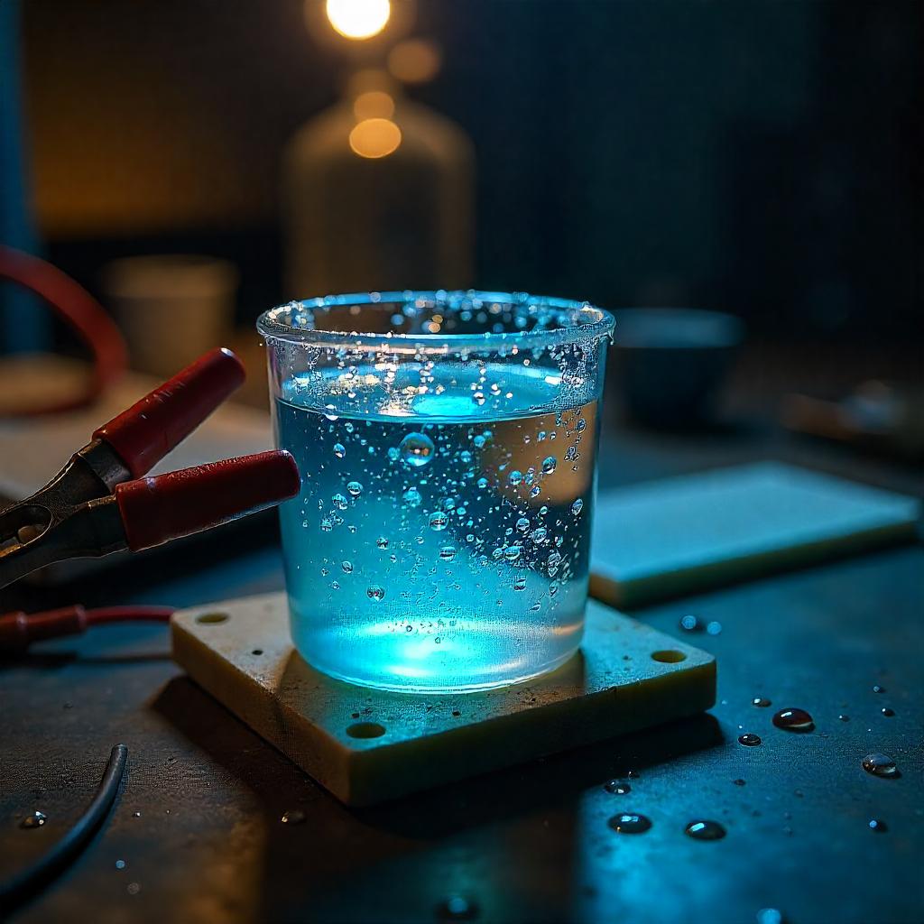
How to Build a Salt Water Resistor?
A saltwater resistor is a simple variable resistor that uses saltwater as the conductive medium. The resistance depends on the salt concentration, electrode spacing, and the container's shape. Here's how you can build one
Resistance vs. Impedance: Understanding the Differences
Resistance and impedance both oppose current flow, but they differ in their application. Resistance applies to both DC and AC circuits, while impedance accounts for frequency-dependent reactance in AC circuits. Learn how these concepts impact electrical and electronic systems.
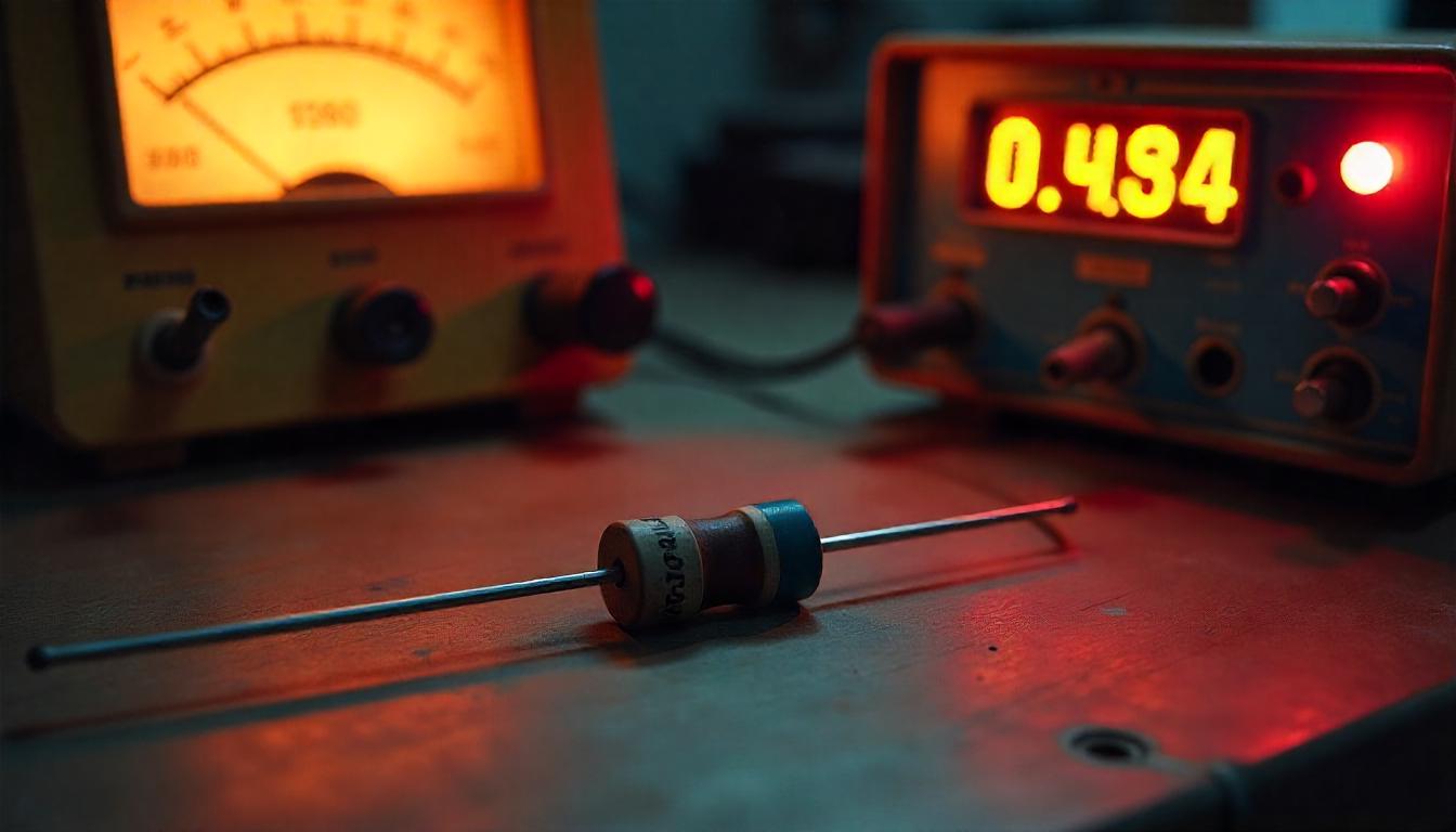
How to Check if a Resistor is Good or Bad Using a Multimeter
Learn how to test a resistor using a multimeter to determine if it is good or bad. This step-by-step guide covers resistance measurement, identifying faulty resistors, and troubleshooting common resistor issues.